During the Repair and Rework, IPC-A-610 or IPC-7711/7721 training courses quite often we get the question which microscope or magnifier is most suited for the visual inspection of a printed circuit board assembly. An answer to this question is not so easy.
 As you might know, according to IPC-A-610 and IPC J-STD-001, the magnification power to be used depends on the size of the component land. In general, this can be divided in a magnification of 1 to 3X for through-hole, 10X for SMD and 20X for fine pitch SMD applications. This means that if all kinds of components have been soldered on a PCB you would have to switch between the different magnification powers quite often even though the standard says that with a mixture of these components (thus lands) the higher magnification might be used for the entire assembly. In practical life this means that with analogue microscopes switching between the magnification powers will be necessary quite often followed by manually adjusting the focus.
The digital era
Nowadays for the visual inspection of Printed Circuit Board Assemblies the operators often use digital microscopes with autofocus. This may have many advantages:
- Manual focusing not necessary anymore (focus automatic)
- More people can watch simultaneously in case of doubt, accept/reject (by monitor)
- The picture/image can be frozen with the press of a button
- Most of the times it is possible to record a short video enabling a view from different angles/sides and discuss things with the operator or client later.
- Zooming in and out is easy, mostly by scrolling with the computer mouse.
- With most software it is even possible to measure dimensions for instance how much side overhang a component has.
Quality
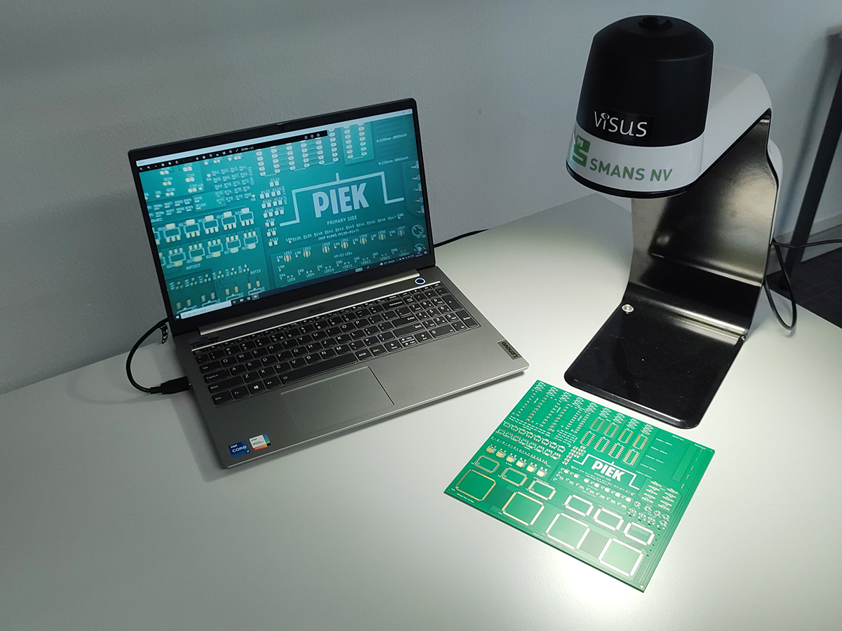
Just as with analogue microscopes quality is an important factor. Especially the autofocus options show a lot of differences in quality. One system in use with PIEK trainings is the VISUS C MORE FULL HD (FHD) Magnification. This system has a very good autofocus. Other systems sometimes fail when for example the board is tilted to check the heel fillet of a Gull-Wing component, and the autofocus adjusts itself to the wrong part of the component.
Before buying a system it is important to do some testing to make sure that it performs up to the expectations.
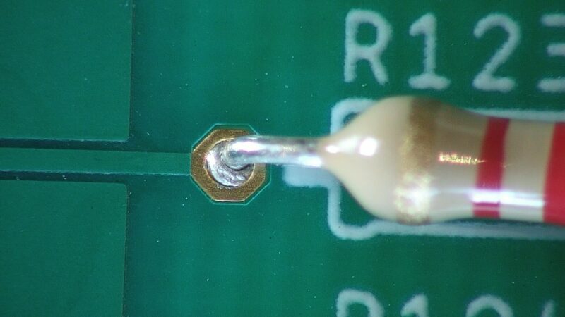
If a layperson would look at this picture, he might say that this digital image with autofocus is not sharp. But for the connoisseur it is obvious. He wants to have a look at the solder in the plated through hole and can see that the solder has not wetted on to the component lead. The autofocus has focused on this part and not on the component housing.
If you would like to know more about the VISUS CMORE FULL HD (FHD) Magnification we use at our trainings you might contact the company Smans or contact PIEK. Also you might watch the introductionary video on Youtube.